Vibration Instrument Config section

1.hmtoggle_arrow1        Sensor & Sampling:


3b- My Instruments - Instrument Config - Sensor & Sampling section


1."Signal type" selector: Type of sampling you want your instrument to perform. The choices are: Acceleration and Velocity. Inclination curves are derived from Acceleration data.
2."Sampling frequency" selector: Adjustable Data sampling rate. Choices are: 4000 Hz, 2000 Hz, 1000 Hz, 500 Hz, 250 Hz, 125 Hz, 63 Hz, 32Hz, 16Hz, 8 Hz and 4 Hz. The power consumption while recording is roughly proportional to the sampling frequency. When recording raw signals the amount of memory consumed is proportional to the sampling frequency. The Memory-Depth indicator in the Setup panel automatically calculates the overall recording time as a function of the selection. for more details on that subject, please refer to chapter 8.3.5.1.1 Sampling Frequency of the VSEW_mk2 User's manual.
2.hmtoggle_arrow1        High-Pass:

3c- My Instruments - Instrument Config - High-Pass Filter section


1."High-Pass Filter" field: Value field for the High-Pass Filter. The value is given in Hz. When measuring accelerations an adjustable-frequency high-pass filter can be added to the measurement path. The high-pass filter is required to measure RMS vibration levels. Otherwise the measured RMS levels would be biased by the DC component. On the other hand, inclination measurements require the measurement of the DC component, so DO NOT use the high-pass filter for inclinations. When measuring velocities, a high-pass filter is automatically placed in the signal path. The field on the left is used to adjust the cutoff frequency. Thanks to its very high resolution, the high-pass filter can be adjusted to frequencies that are extremely low relative to the sampling frequency.For more details on that subject please refer to chapter 6.5.1 Measurement of the VSEW_mk2 User's Manual.
2."High-Pass On" checkbox: The High-Pass filter can be selected or deselected by clicking on the checkbox.
3.hmtoggle_arrow1        Auto-Recording:

3d- My Instruments - Instrument Config - Auto-Recording section


These settings adjust the trigger threshold and the inactivity period. Once the instrument is placed in Auto-Rec mode it switches between two states:

Waiting for inactivity        While recording, the instrument waits for inactivity. Inactivity is defined as “signal that stays below the threshold on all three axes for a time longer than the inactivity period”.
When inactivity is detected the instrument stops the ongoing recording. Therefore the inactivity time defines the minimum amount of time that the instrument will record, once triggered. The recording will keep going if the signal keeps passing the threshold while the recording is ongoing.


1."Auto recording threshold (float)" field: Value field for triggering the recording. Waiting for activity. While in inactive mode the instrument waits for activity. Activity is defined as “signal that transitions through the threshold on at least one axis”. The signal must be below, then above the threshold to trigger the recording. When activity is detected the instrument creates a new record and starts recording. The threshold is the same on all axes. More information on that subject can be found in chapters "6.9 manual Recording" and "6.10 AutoRec recording" of the VSEW_mk2 User's Manual.
2."Threshold units" selector: The statistic and the recording threshold can be set either in "g" or "m/s^2 when the statistic is Acceleration. Units will be "m/s" when instrument is configured for Velocity.
3."Minimum quiet time": While recording, the instrument waits for inactivity. Inactivity is defined as “signal that stays below the threshold on all three axes for a time longer than the inactivity period”. When inactivity is detected the instrument stops the ongoing recording. Therefore the inactivity time defines the minimum amount of time that the instrument will record, once triggered. The recording will keep going if the signal keeps passing the threshold while the recording is ongoing.
4."Timer / WiFi" selector: This control defines the action to take when the timer is engaged, or if the recording is started via WiFi™ through the server. The choices are: "Record" and "Auto-recording. Record: The recording will start once the timer has reached the specified time and date. Auto-recording: The instrument will go to Auto-Rec mode once the timer has reached the specified time and date.
4.hmtoggle_arrow1        Recording:

3e- My Instruments - Instrument Config - Recording section


1."Log interval" selector and field: The log interval defines the time between two successive recorded points when the instrument is recording signal statistics or RMS level statistics. When recording either type of statistics the min, max and average are reset at the beginning of each log interval. Then the instrument observes the signals or levels for the duration of the log interval, and updates the min, max and averages accordingly. At the end of the log interval the selected statistics are written to memory. Then the next log interval is started… and so on until the recording is stopped or the memory is exhausted. The log interval is only relevant when recording statistics. When recording raw signals the time between two successive samples is simply the sampling period. The log interval can be adjusted from 125 ms to 2 H in increments of 125 ms. Note: When recording statistics the amount of memory consumed is inversely proportional to the log interval. The Memory-Depth indicator in the Setup panel of the Instrument Manager automatically calculates the overall recording time as a function of the selection.
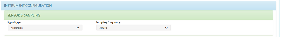
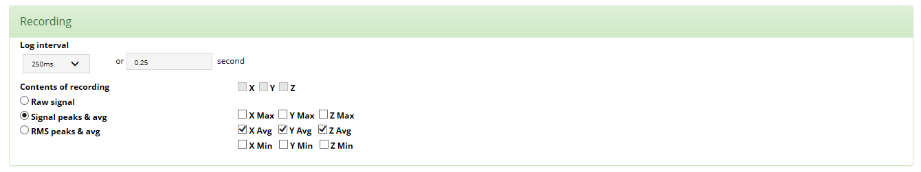
2."Content of recording" buttons and check boxes: You must first select one of the three following buttons. These buttons specify whether raw signals, signal statistics or RMS level statistics are being recorded. In either case the user must choose the axes, and optionally the types of statistics to record. To select or deselect an axis or statistic, simply press on the corresponding check boxes. Note: In order to record inclinations select “Acceleration”, then select “Signal peaks & avg” and select at least the X-avg, Y-avg and Z-avg selectors. The inclinations are calculated from those acceleration measurements. The amount of memory consumed while recording is proportional to the number of channels and statistics selected.
a."Raw signal" button: The signal (acceleration or velocity) is recorded at the sampling frequency.
b."Signal peaks & avg" button: The Signal Statistics processing captures the min, max and average of the acceleration or velocity signal over an adjustable recording (log) interval. For each new interval the statistics are cleared, then the statistics are updated during the course of the interval, then at the end of the interval the statistics are recorded, and a new interval is started.
c."RMS peaks and avg" button: the RMS-Level signal is squared to calculate the instantaneous power. The instantaneous power is low-pass-filtered with an adjustable time constant to produce an average. A short time constant provides an average that is capable of tracking fast transients, while a longer time constant provides a smoother and less noisy average. A typical fast time constant is around 100ms. While a typical long time constant is around 1s. Finally the square-root of the power is taken to present RMS vibration or velocity levels. The RMS vibration levels can be displayed in linear or dB scale.
d.Axes check boxes: From the "Signal type" and the previous selection, the maximum recording content for the three axes is automatically checked. You can reduce the recording to the axes you want and Max, Avg, Min values you want.
5.hmtoggle_arrow1        RMS Response:

3f- My Instruments - Instrument Config - RMS Response section


1."Time constant" selector and field: If recording RMS levels, select the time constant used to smooth the measured levels for min and max. Choose a time constant around 125 ms to be able to detect short transients. Choose a time constant around 1s to provide cleaner and more stable RMS levels. Or adjust to another value, as required by the application. The selector choices are: "Impulse" = 0.035 s, "Slow" = 1.0 s, "Fast" = 0.125 s and "--" = your value.
6.hmtoggle_arrow1        Other settings:

3g- My Instruments - Instrument Config - Other settings section


1."Instrument's Time Zone" selector: The instrument is normally setup with the UTC. If you want the records to be adjusted to the Local Time of your instrument, you must specify it by selecting the proper time zone. For instance New Yorc city Time Zone is GMT-4H00 during Summer Time and GMT-5H00 during Winter Time.