 8 Instrument Manager Application

Contents
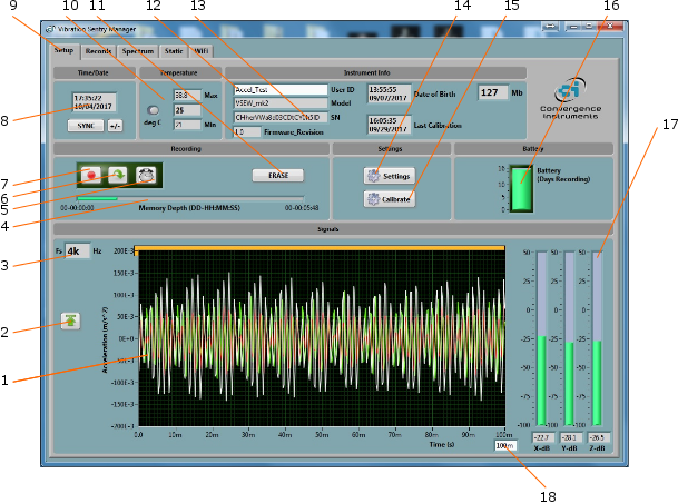
Figure 9 Setup Tab
| 1. | Real-Time Signals |
| 2. | Auto-Range Button |
| 3. | Sampling Frequency Indicator |
| 4. | Memory Fill Indicator |
| 5. | Timer Button |
| 6. | AutoRec Button |
| 7. | Record Button |
| 8. | Instrument Time Indicator |
| 9. | Tab selector |
| 10. | Instrument Temperature Indicator |
| 11. | Erase Button |
| 12. | Instrument Custom ID |
| 13. | Instrument Information |
| 14. | Settings Button |
| 15. | Calibration Button |
| 16. | Battery Condition, Charge and Recording Time Field |
| 17. | RMS Level Indicators |
| 18. | Display Length |
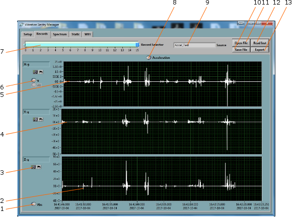
Figure 0 Record Tab
| 1. | Absolute/Relative Time Scale Button |
| 2. | Z-Axis Recorded Data |
| 3. | Pan and Zoom Buttons |
| 4. | Y-Axis Recorded Data |
| 5. | X-axis Recorded Data |
| 6. | Scale Buttons |
| 7. | Record Number Selector |
| 8. | Acceleration/Inclination Display Mode |
| 9. | Data Source |
| 10. | File Save Button |
| 11. | File Open Button |
| 12. | Instrument Download Button |
| 13. | Export Button |
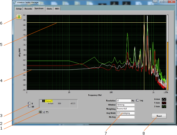
Figure 11 Spectrum Tab
| 1. | Cursor, Zoom and Pan controls |
| 2. | Cursor values display |
| 3. | Scale buttons |
| 4. | Spectrum |
| 5. | Cursor |
| 6. | Auto-scale button |
| 7. | Spectral controls |
| 8. | Spectrum reset button |
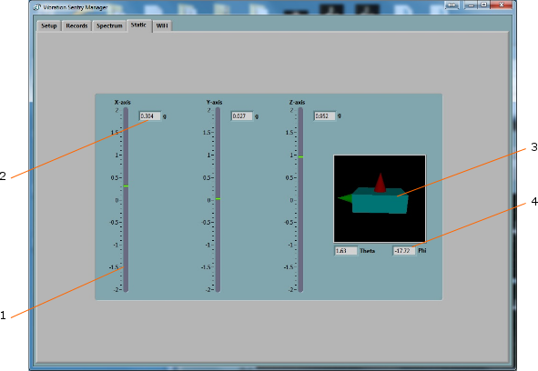
Figure 12 Static Tab
| 1. | Static axis indicator |
| 2. | Static digital display |
| 3. | Inclinometer graphic display |
| 4. | Inclinometer angle displays |
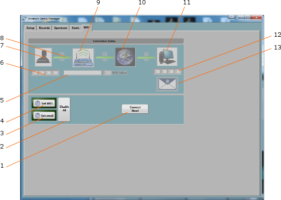
Figure 13 WiFi Tab
| 1. | Connection Test Button |
| 2. | Disable All WiFi Button |
| 3. | Email Setup Button |
| 4. | WiFi Setup Button |
| 5. | Name (SSID) of WiFi Access Point or Router |
| 6. | IP Address of Instrument |
| 7. | Instrument WiFi Active Indicator |
| 8. | Link Indicator |
| 9. | Router or Access Point Connected Indicator |
| 10. | Network Connected Indicator |
| 11. | Server Connection Indicator |
| 12. | Server IP Address |
| 13. | Email Connection Indicator |